
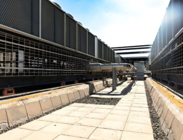
How to Optimise Chilled Water Waste Heat Recovery Without Compromising COP
The Parasitic Dilemma in Industrial Heat Recovery
Recovering heat from a chilled-water plant appears straightforward because a chiller rejects substantial thermal energy through its condenser. The engineering challenge is that useful recovery normally requires a temperature difference, while refrigeration efficiency depends on keeping the condensing temperature as low as practical. If the recovery circuit forces the condenser to operate at a higher saturated discharge temperature, the compressor must work against greater pressure lift. The recovered heat may then come with an electrical penalty large enough to erode, or even eliminate, the expected energy benefit.
The objective is therefore not to extract the highest possible water temperature from every operating condition. It is to design a recovery system that captures useful low-grade heat while preserving the chiller”s baseline operating envelope. That means separating hydraulic functions, selecting heat exchangers for close approach temperatures, and matching the recovered heat to loads that genuinely operate at moderate temperatures. Properly configured, the system can reduce boiler or electric-heater demand without turning the chiller into an inefficient high-lift heat pump.
Thermodynamics of the Condenser Lift Penalty
A mechanical chiller rejects the cooling load plus compressor input at its condenser. As condensing saturated discharge temperature rises, condensing pressure also rises, increasing the pressure ratio across the compressor. Compressor power consequently increases, while refrigeration capacity and COP generally decline. The effect is particularly important in systems that use a recovery heat exchanger upstream of, or in series with, the cooling tower. A recovery load that demands a fixed high outlet temperature can establish a permanent artificial lift even when the building or process only needs low-temperature heat.
In practical design discussions, a commonly used planning estimate is a COP reduction of approximately 2% to 4% for each 1°C of artificial condensing-temperature lift. The exact value depends on refrigerant, compressor type, evaporating conditions, condenser approach, part-load state, and control strategy, so it should be validated against manufacturer performance data rather than treated as a universal constant. Even so, the magnitude is sufficient to justify detailed modelling. A few degrees of unnecessary lift can consume much of the energy saved by reducing boiler operation.
| Recovery strategy | Typical thermal objective | Primary risk | Preferred engineering response |
|---|---|---|---|
| Full-condensing heat recovery | High-temperature water for demanding loads | Persistent compressor lift and reduced chiller COP | Use only where the high-temperature load is substantial and coincident with cooling |
| Parasitic-neutral low-grade recovery | Preheating, reheat, or moderate-temperature process water | Insufficient temperature difference at low load | Use close-approach exchangers, bypass control, and realistic sink temperatures |
| Hybrid recovery with thermal storage | Capture intermittent condenser heat for later use | Storage losses, control complexity, and oversized equipment | Size storage from measured load profiles and operate recovery only within the efficient envelope |
The distinction between available heat and useful heat is critical. Research on industrial waste heat recovery emphasizes that temperature lift, operating schedules, heat quantity, and end-use requirements determine whether recovery produces a net benefit. This research on industrial waste heat recovery reinforces the need to manage lift rather than valuing every rejected kilowatt-hour equally. A low-temperature heat sink available throughout the year can be more valuable than a high-temperature sink that operates for only a few peak hours.
Hydraulic Decoupling and Flow Control Architecture
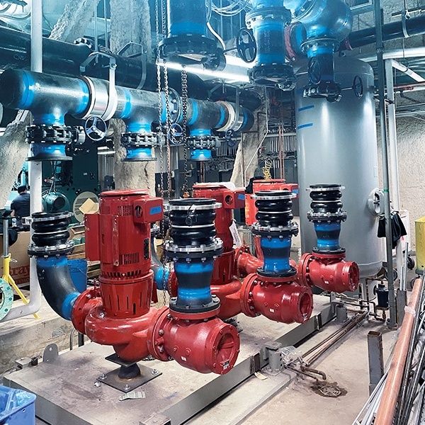
Hydraulic decoupling allows the recovery circuit to operate without destabilising the condenser water circuit. In a typical side-stream arrangement, a controlled portion of condenser water passes through a recovery plate heat exchanger and then returns to the condenser loop or cooling-tower path. The main condenser flow remains available to satisfy chiller and tower requirements, while the recovery branch responds to the actual heating demand. This approach reduces the risk that a recovery pump, restrictive exchanger, or partially closed valve will starve the condenser or alter flow beyond the chiller manufacturer”s allowable range.
Three-way modulating bypass valves and variable-speed recovery pumps solve different parts of the control problem. A three-way valve can maintain a stable condenser-side flow split by routing excess water around the recovery exchanger. It is comparatively simple and can provide fast temperature control, but it may waste pumping energy if the branch flow remains high when the demand is small. A variable-speed pump can reduce flow and pumping power at part load, although it requires dependable differential-pressure control, minimum-flow protection, and careful coordination with the chiller”s condenser-flow requirements. In many installations, a modulating valve provides the primary temperature safeguard while a variable-speed pump trims flow over a wider operating range.
Controls should prioritise chiller protection before heat recovery output. The recovery loop should enable only when condenser flow, leaving-water temperature, and heating demand are within permitted limits. If condenser leaving-water temperature approaches the upper design boundary, the bypass should open or the recovery pump should reduce speed. If the recovery sink cannot accept heat, the system should return smoothly to normal heat rejection rather than forcing the chiller to maintain an unwanted temperature. Variable-capacity compression and water-to-water heat-pump concepts demonstrate the value of modulation, but recovery controls still need to be based on the specific chiller, refrigerant circuit, and manufacturer sequence.
- Establish the chiller manufacturer”s minimum and maximum condenser flow, entering-water temperature, leaving-water temperature, and allowable pressure-drop limits.
- Measure the available condenser flow and temperature at representative load conditions before selecting the recovery branch.
- Use a bypass or variable-speed strategy to maintain condenser stability when heating demand changes faster than cooling demand.
- Interlock recovery with high condensing pressure, low flow, exchanger freeze protection, pump failure, and abnormal differential pressure.
- Trend condenser approach, compressor power, recovered heat, and heating-side temperature to verify that the system is producing net savings.
Heat Exchanger Sizing and Fouling Resistance Margins
For low-grade recovery, a plate-and-frame heat exchanger is often the most effective choice because its high heat-transfer coefficient and compact geometry can support close approach temperatures. A design approach of 1°C to 2°C can allow useful heat transfer without demanding an unnecessarily high condenser temperature. The exchanger should be selected from actual design flow rates and temperature profiles, not from nominal chiller capacity alone. Oversizing can increase first cost and pressure drop, while undersizing forces a wider approach and may encourage operators to raise the condensing setpoint to recover the desired water temperature.
Open cooling-tower water presents a different challenge from a clean closed heating loop. Suspended solids, biological growth, corrosion products, and mineral scale can reduce the effective overall heat-transfer coefficient. A fouling allowance therefore needs to be included in the selection calculation, but an excessive allowance can create an exchanger that is needlessly large and hydraulically restrictive. Water treatment, filtration, blowdown control, accessible channels, and appropriate plate materials are part of the heat-recovery design, not separate maintenance details.
The U.S. Department of Energy”s assessment of waste heat recovery identifies heat-exchanger surface selection and fouling mitigation as important determinants of economic viability. The energy.gov technology assessment also stresses that recoverable energy depends on temperature, quantity, composition, minimum allowable temperature, and operating schedule. In a chilled-water plant, those constraints translate directly into exchanger sizing, cleaning access, and the choice of heat sink.
- Specify a close approach based on measured operating temperatures, with separate calculations for design, part-load, and fouled conditions.
- Include differential-pressure transmitters across both exchanger circuits so fouling and blockage can be detected before heat-transfer performance collapses.
- Provide isolation valves, drain points, vents, spare gaskets where appropriate, and clean-in-place connections that permit maintenance without prolonged plant downtime.
- Confirm that plate materials, gasket compounds, and channel velocities are compatible with condenser-water chemistry and the heating-side fluid.
- Trend recovered kilowatts against flow and temperature difference to distinguish fouling from low demand or sensor error.
Matching Realistic Low-Grade Thermal Demands
The strongest applications are loads that can use condenser heat at moderate temperatures. Boiler make-up water preheating is a practical example because even a modest temperature rise can reduce the fuel required to produce steam or hot water. Other opportunities include domestic hot-water preheating, air-handling-unit preheat, terminal reheat coils, low-temperature radiant systems, process wash water, and selected manufacturing streams. The appropriate sink depends on water quality, hygiene requirements, code obligations, storage arrangements, and the timing of demand.
High-temperature domestic hot water or process loads require particular caution. If the required delivery temperature is materially above the natural condenser-water temperature, the chiller may need artificial condensing lift or a separate heat-pump stage. That can still be sensible where the load is large and continuous, but it should not be assumed that all condenser heat is equivalent to boiler-grade heat. A staged arrangement is often more efficient: use recovered heat for preheating, then allow a conventional boiler, electric heater, or dedicated heat pump to provide final temperature lift.
Load coincidence determines the financial result. A recovery system needs useful cooling and useful heating at the same time, or it needs storage sized around a measured mismatch. Continuously operated buildings, hospitals, data-intensive facilities, and industrial plants with year-round internal cooling are often stronger candidates than seasonal office buildings. Before approving capital expenditure, map hourly or sub-hourly condenser rejection against heating demand, calculate the fraction of recovered heat that can actually be used, and include pump power, maintenance, water treatment, exchanger cleaning, and control-system costs.
| Potential heat sink | Why it suits low-grade recovery | Design caution |
|---|---|---|
| Boiler make-up water | Preheating reduces firing demand without requiring final boiler temperature from the chiller | Verify feedwater treatment, storage, and allowable temperature limits |
| Terminal reheat coils | Often operate at moderate water temperatures and can coincide with cooling and dehumidification | Check seasonal zoning, minimum ventilation loads, and valve authority |
| Air-handling-unit preheat | Provides a broad, controllable demand during cold-weather operation | Protect coils against freezing and confirm that demand coincides with chiller operation |
| Domestic hot-water preheating | Reduces the load on final heating equipment | Address storage, temperature control, hygiene, and cross-connection protection |
| High-temperature process water | Can deliver substantial savings where demand is continuous | May require a separate heat-pump lift stage and should not be imposed on the chiller by default |
Engineering High-Yield Heat Recovery Without Compromise
Net-positive chilled-water heat recovery begins with respect for the baseline refrigeration system. The condenser should not be treated as an unlimited source of high-temperature heat. Its value is greatest when the recovery circuit accepts the naturally available temperature, transfers that heat through a low-approach exchanger, and delivers it to a sink that needs only a moderate temperature increase. This preserves compressor efficiency while reducing boiler or electric-heater consumption.
Three design principles provide a reliable foundation: hydraulically separate the recovery branch from the required condenser flow, size the plate heat exchanger for close approach under clean and fouled conditions, and target loads with strong year-round coincidence. Commissioning should confirm actual flow, temperature, pressure drop, compressor power, recovered heat, bypass position, and heating-load response. Operators should also establish alarm thresholds for rising condenser approach, exchanger differential pressure, inadequate flow, and persistent high condensing temperature. These checks turn a promising energy concept into an accountable plant asset that protects uptime, controls maintenance exposure, and delivers measurable savings over its operating life.
- Record the chiller”s unrecovered baseline COP across representative load and ambient conditions.
- Verify that recovery operation does not create sustained artificial condensing-temperature lift beyond the approved design envelope.
- Test bypass valves, variable-speed pumps, safeties, and failure modes under both full and partial heating demand.
- Compare measured recovered energy with the heating load that is genuinely displaced, rather than reporting condenser heat captured alone.
- Schedule exchanger inspection and cleaning from differential-pressure and performance trends, supported by a documented water-treatment program.
Comments are closed.