
The Silent Threat of DX Evaporator Mal-Distribution in Mission-Critical Systems
In a mission-critical DX system, a normal rack-level suction superheat reading can create dangerous confidence. A multi-circuit evaporator may be receiving refrigerant unevenly even while the common suction line appears stable. One circuit can be starved, carrying excessive superheat and using only part of its available surface area, while another circuit receives too much liquid and approaches an unsafe compressor return condition. The combined reading averages these conditions instead of revealing them.
The consequences extend beyond a modest loss of capacity. Uneven refrigerant feed reduces effective enthalpy exchange, increases compressor run time, and can create temperature variation across a data center or cleanroom coil. In applications where airflow and load are already tightly controlled, a partially inactive circuit may force the system to operate at lower suction pressure or higher condensing pressure to maintain the space setpoint. That combination consumes energy while leaving less capacity available during peak thermal events.
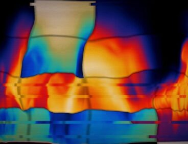
The most difficult failure pattern is a false control problem. A thermostatic expansion valve or electronic expansion valve may appear to hunt because its sensor sees the aggregate response of an unstable evaporator. Meanwhile, liquid-rich circuits can send intermittent liquid toward the suction header, creating the conditions for compressor slugging. Systematic surface temperature mapping provides a circuit-level view of this behavior. It turns a misleading bulk measurement into a thermal map that can identify airflow distortion, nozzle restriction, feeder imbalance, and valve response problems before they become equipment failures.
- Bulk superheat shows the combined outlet condition, not the condition of every circuit.
- Cold and warm patterns across the coil can identify liquid-rich and starved paths.
- Mapping should be performed under controlled airflow and stable load, with appropriate safety procedures.
Thermodynamic Realities of Multi-Circuit Coil Imbalance
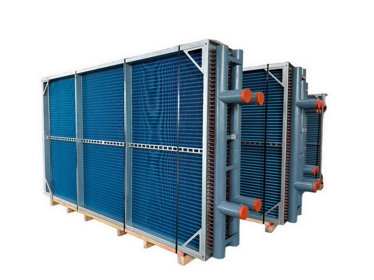
A multi-circuit evaporator depends on the distributor, nozzle, feeder tubes, and circuit geometry to divide two-phase refrigerant in a predictable way. That division is inherently sensitive to pressure drop, vapor quality, velocity, orientation, and piping arrangement. A small amount of debris in a nozzle can restrict one path, while an elevation difference or unequal feeder length can change the local pressure conditions enough to alter the phase split. Instead of each circuit receiving a comparable refrigerant mass flow, one path may receive mostly vapor and another a liquid-heavy mixture.
Airflow adds a second source of variation. A filter loading pattern, damper position, fan discharge effect, blocked coil section, or poor transition can produce different face velocities across the coil. Circuits under high sensible load may evaporate refrigerant rapidly and become warm at the outlet. Circuits under low airflow may retain more liquid and show a colder surface. Because both latent and sensible loads vary across the coil face, refrigerant distribution cannot be evaluated independently from air distribution.
A single suction temperature sensor cannot reliably detect this localized behavior. Its reading is influenced by mixing in the suction header and downstream piping, so a warm starved circuit can offset a colder circuit that is carrying unevaporated refrigerant. Pressure and temperature measurements remain essential, but they need to be paired with circuit-level observations. The supplied material from irc.wisc.edu research documentation is not available in a readable form for independent verification, so specific claims from that file should not be treated as validated empirical findings. The engineering principle remains clear: maldistribution can reduce usable coil capacity and cause control instability even when common-line readings look acceptable.
For valve diagnosis, superheat should be considered alongside subcooling, airflow, and coil condition. A TXV balances bulb pressure, evaporator pressure, and spring force, and similar symptoms can arise from a restricted valve, low charge, dirty coil, or inadequate airflow. The practical implication is important: no single pressure or temperature value proves the root cause. A thermal map supplies the spatial evidence needed to determine whether the problem is localized to refrigerant feed or spread across the airside of the coil.
Distinguishing Root Causes across the Evaporator Assembly
Root-cause separation begins by comparing the thermal pattern with suction-line behavior. A partially blocked distributor nozzle often produces one or more consistently warm circuits while adjacent circuits remain comparatively cold. Airflow mal-distribution usually follows the geometry of the coil face, with a broad warm or cold region that corresponds to a fan discharge pattern, blocked filter area, damper position, or external obstruction. TXV hunting tends to produce a time-varying pattern, with several circuits changing temperature as the valve repeatedly opens and closes.
Mechanical inspection is equally important. Feeder lines with different lengths, excessive bends, unsupported sections, or elevation changes can create unequal pressure losses. Brass orifice wear may enlarge a passage and overfeed a circuit, while corrosion, brazing debris, or filter material may restrict it. Before replacing a valve, verify that the bulb is correctly located and insulated, sensors are properly installed, and the coil is clean. Qualified personnel should follow the equipment manufacturer”s service instructions, isolate electrical power, and use refrigerant-handling procedures appropriate to the refrigerant in service.
| Likely condition | Typical presentation | Suction behavior | Thermal gradient signature |
|---|---|---|---|
| Distributor nozzle restriction | Reduced capacity with a persistent circuit imbalance | Often low suction pressure or elevated common superheat | One or more warm, starved passes beside colder normal passes |
| Airflow mal-distribution | Capacity loss tied to fan, filter, damper, or duct conditions | May remain relatively stable despite uneven coil loading | Broad spatial pattern following the face-velocity profile |
| TXV or EEV hunting | Oscillating capacity, temperature, and superheat | Superheat and suction pressure fluctuate with valve movement | Patterns shift repeatedly rather than remaining fixed |
| Overfeeding or liquid carryover | Low superheat and risk of wet suction return | Common superheat may fall intermittently | Localized very cold circuits, frosting, or rapidly changing cold bands |
Research on smart refrigerant distribution in finned-tube evaporators is intended to address this exact engineering problem, namely how improved circuit feeding can preserve heat transfer effectiveness when airflow and load are not uniform. The provided authoritative distribution study should be reviewed for its stated test conditions and limitations before applying its results to a particular coil. Laboratory findings are not a substitute for field measurements, but they support the value of balancing refrigerant feed rather than accepting an averaged outlet condition.
Step-by-Step Surface Temperature Mapping Protocol
Surface mapping is most useful when the system is deliberately stabilized. Record operating conditions before touching the coil, including entering and leaving air temperatures, airflow or fan speed, suction and liquid pressures, refrigerant type, valve command, compressor staging, filter condition, and space load. The objective is not to capture a dramatic transient. It is to establish a repeatable baseline that can later be compared with the system after corrective work.
- Stabilize the system. Lock the airflow at a known operating point, maintain a reasonably constant cooling demand, and allow the coil and refrigerant circuit to reach steady operation. Avoid mapping during defrost, startup, compressor staging, rapid setpoint changes, or active alarm recovery. Confirm that access is safe and that rotating, electrical, and refrigerant hazards are controlled.
- Scan the coil with calibrated infrared equipment. Capture the face, headers, return bends, and accessible feeder regions. Correct for emissivity, reflective metal surfaces, viewing angle, and insulation gaps. Use a consistent camera position and record the ambient conditions. Cold bypass streamers, isolated cold bends, and warm starved passes should be marked on a coil diagram rather than interpreted from a single image.
- Install contact thermistors at circuit outlets. Attach calibrated sensors to clean, representative tubing surfaces using suitable thermal paste and secure insulation. Avoid placing a sensor on a braze joint, directly in radiant view of a hot component, or where mechanical strain can alter contact. Label every circuit and document sensor location, attachment method, and calibration offset.
- Log temperatures against saturation pressure. Record each circuit outlet temperature at a useful sampling interval while simultaneously recording suction pressure and valve command. Convert suction pressure to saturation temperature for the actual refrigerant, then calculate circuit-level superheat where the pressure reference is appropriate. Repeat during controlled load changes to distinguish a fixed restriction from a dynamic control response.
Infrared imaging is a screening method, not a replacement for contact measurement. A shiny copper tube can produce a misleading apparent temperature, and insulation or moisture can hide the true surface condition. Contact sensors provide better trend data, but they must be installed consistently. When comparing circuits, sensor error should be smaller than the temperature differences being used to make a decision. A practical record includes the original thermal images, annotated circuit numbers, pressure logs, valve position, fan status, and environmental conditions.
Mapping should also include time behavior. A circuit that remains warm for an hour suggests a different fault from a circuit that alternates between very cold and warm every few minutes. Correlating outlet temperature with suction pressure and valve position reveals whether the evaporator is responding slowly, whether the valve is overcorrecting, or whether a fixed distribution defect remains unchanged. This time-resolved evidence is particularly valuable in data centers, where a stable average room temperature can conceal localized coil and compressor stress.
Corrective Engineering Actions and Long-Term Coil Balancing
Corrective work should follow the measured failure mode. If the distributor is restricted or the phase split is demonstrably poor, inspect and clean the inlet path, verify nozzle selection, and replace damaged or eroded orifice components. Precision distributor nozzles and properly matched orifice rings can improve liquid-phase splitting, but they must be selected for the refrigerant, capacity, pressure drop, circuit count, and operating envelope. Replacing a nozzle without confirming the design basis can move the imbalance from one circuit to another.
Electronic expansion valve control requires the same discipline. PID gains, minimum and maximum opening limits, sensor filtering, and response timing should reflect the verified thermal response of the coil. Excessive gain can create destructive hunting, while excessive filtering can delay correction and permit liquid carryover during load changes. Any controller adjustment should be made with trend data and manufacturer limits. Service documentation for electronic refrigeration controllers also emphasizes correct sensor installation, dedicated power arrangements, suitable pressure transducers, and protection of valves and sensors during brazing and commissioning.
Airside corrections are often the most economical solution. Inspect filters, dampers, fan rotation, fan speed control, duct transitions, coil cleanliness, and obstructions immediately upstream of the coil. If the face velocity profile is distorted, refrigerant-side balancing alone may not restore stable performance. In larger air-handling systems, airflow measurements across a grid can be compared directly with the thermal map. The goal is to correct the cause of the uneven load before fine-tuning the refrigerant control.
- Record a post-repair thermal map under the same baseline conditions.
- Verify circuit outlet temperatures, common suction superheat, subcooling, and compressor protection status.
- Trend valve position and suction pressure during normal and peak loading.
- Repeat mapping after filter replacement, fan changes, coil cleaning, or major control modifications.
A predictive maintenance program should treat the thermal map as a reference fingerprint. Gradual changes in a previously uniform pattern can indicate fouling, feeder restriction, airflow deterioration, or sensor drift before capacity alarms appear. Scheduled comparisons are especially valuable in facilities where loss of cooling can affect servers, process equipment, or controlled environments. Every intervention should preserve the documentation needed for future technicians, including circuit diagrams, sensor locations, operating conditions, and acceptance criteria.
Securing Reliability Through Precision Evaporator Diagnostics
Circuit-level surface mapping removes the blind spot created by relying on a single suction superheat value. It shows where refrigerant is evaporating effectively, where airflow is failing to deliver the expected load, and where liquid may be bypassing the intended control point. Used with pressure, subcooling, valve-command, and airflow data, it allows engineers to separate a distributor restriction from an airside problem or a genuine valve-control fault.
The operational benefits compound over time. A better-balanced evaporator can recover usable coil capacity, improve enthalpy exchange, reduce unnecessary compressor runtime, and lower the likelihood of liquid slugging. For mission-critical facilities, the result is not merely improved efficiency. It is greater compressor life, more predictable control, fewer emergency callouts, and stronger confidence that the system will respond to its next high-load event. Surface thermometry mapping should therefore become a standard commissioning, troubleshooting, and periodic auditing practice wherever DX evaporators support continuity-critical cooling.
Comments are closed.